
Fixing the Cable or Making a Test Box (Rev. 3.xx only)
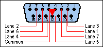
Using the pin numbers embossed on the SuperTimer Lane Interface
Card connector, the cable wiring is as follows:
| Lane | Pin | Comments |
|---|---|---|
| Finish Cable | ||
| 1 | 10 | Each Lane switch is a normally-open set of contacts between the Pin and Common. |
| 2 | 7 | |
| 3 | 2 | |
| 4 | 13 | |
| 5 | 11 | |
| 6 | 6 | |
| 7 | 3 | |
| Start Cable | ||
| Start | 7 | Closed when magnet is near, opens at start. |
The Common (ground) for all of the lanes and the Start gate is pin 4, 5, or 12. These three pins are all wired to the computer case (ground) and are interchangeable.
The 15-pin connector is available from many computer supply stores, but is not available from Radio Shack.
Pins 1, 8, 9, and 15 are wired directly to the computer's 5-volt digital power supply. DO NOT CONNECT TO THESE PINS!!!
Notice that the Start Gate and Lane 2 connect to the same pin
on the corresponding connector. This is the reason that if you have the
cables plugged into the wrong connectors, Lane 2 will look like the Start
Gate, and the Start Gate will look like Lane 2.
Copyright © 2003 SuperTimer